UML Diagram in Software Engineering is a graphical language used to envision, build, and document the model of a software system.
Suppose offers a simple way to write a system’s drawings with conceptual things such as the working process and function performed by our software, as well as our Programming language statements, such as database schema and reusable code of software in different components for different working.
In this post, we will gain knowledge of all the types of UMLs, such as Class diagrams, Collaboration diagrams, Activity diagrams, State diagrams, and Use case diagrams with their examples.
Introduction:
UML (Unified Modeling Language) is a general language used to model our software in OOSE (object-oriented Software Engineering). Unified Modeling Language includes a set of symbol notation methods used to create our software visual models.
UML combines techniques from database modeling, our work modeling, classes, object modeling, and significant component modeling that can be used throughout the SDLC (software development life cycle) and in different software implementations.
Modeling:
There is a difference between a UML model and the set of diagrams used to design a UML model of software. A diagram used to design a software model partially represents a system software.
The model also contains software documentation describing the components and diagrams, Such as written class diagrams and use cases.
UML diagrams represent two different views of a system model:
Static or Structural View:
This view highlights the static or structural view of the system using objects, operations, attributes, and their relationships. For example, the relationship between different classes is shown in the Class Diagram and the Use Case Diagram.
Dynamics of Behavioral View:
This view highlights the system’s dynamic or behavior by exposing collaborations between objects and unchanging the states for other states’ states of objects. for example SD (Sequence Diagram), AD(Activity Diagram), SM (State Machine) diagram.
Diagram Overview:
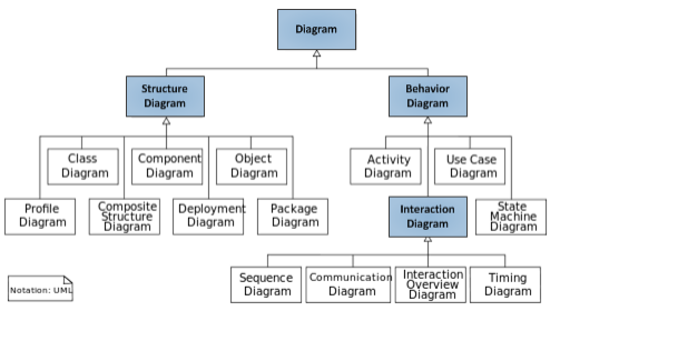
Structure Diagram:
These diagrams describe the things present in the software since They represent the software structure and the software model’s architecture.
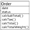
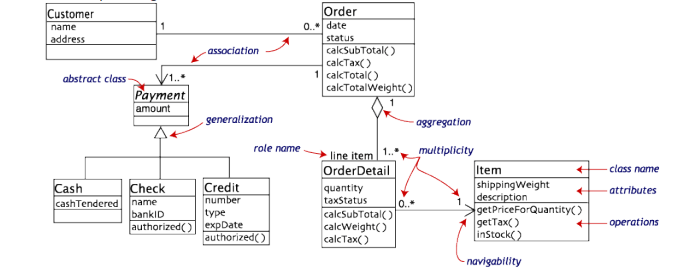
1. UML Class Diagram in Software Engineering:
Define the structure of a software system by describing the system classes, their attributes, and the relationships among them.
In the Class Diagram, there are three major attributes:
1: Class Name(Order)
2: Data member (date, status)
3: Functions (cal subtotal…..)
2. UML Component Diagram in Software Engineering:
Define how a software system is divided into components and show the dependencies among these components.
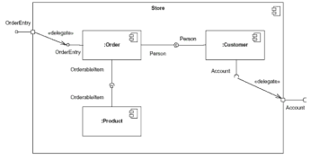
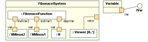
3. UML Composite Structure Diagram in Software Engineering:
Define the internal structure of a class and collaboration between the software structure.
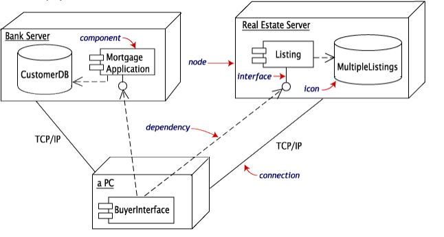
4. UML Deployment Diagram in Software Engineering :
Define the hardware that is used in the manufacturing of software and the execution environments of software that are deployed on the hardware.
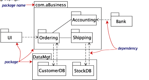
5. UML Package Diagram in Software Engineering:
Define how a system is divided logically into groupings by showing the reliance among these groupings.
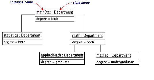
6. UML Object Diagram in Software Engineering:
Shows a full or half view of the structure of an example modeled system at some specific interval of time.
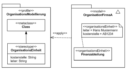
7. UML Profile Diagram in Software Engineering:
A profile diagram is any diagram created in a <<Profile>> package. Profile provides a means of extending the UML. They are based on additional stereotypes and Tagged Values applied to UML elements, Connectors, and their components.
Behavior Diagram:
UML Behavioral Diagrams represent the elements of a system that are dependent on time and convey the system’s flux concepts and connections. The elements in these diagrams look like the verbs in a natural language, and the relationships that connect them typically convey the passage of time.
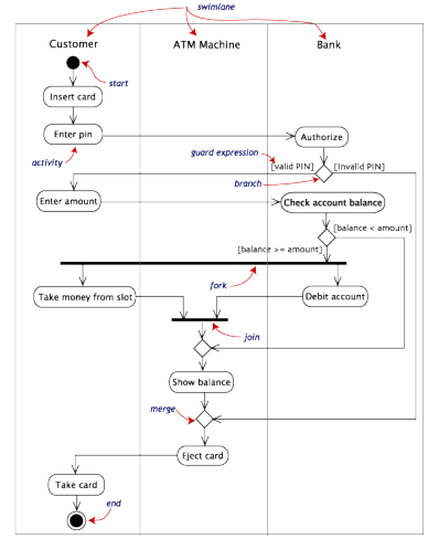
1. UML Activity Diagram in Software Engineering:
Define the functional workflow of components with step-by-step in a system.
Example of Activity Diagram.
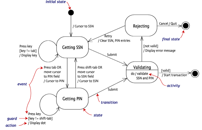
2. UML State Transition Machine in Software Engineering:
Define the state transitions of the system and how a system switches from one state to another.
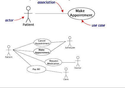
3. UML Use Case Diagram in Software Engineering:
Define the system’s functionality regarding actors, their aims represented as use cases, and any dependencies among them.
Interaction Diagrams:
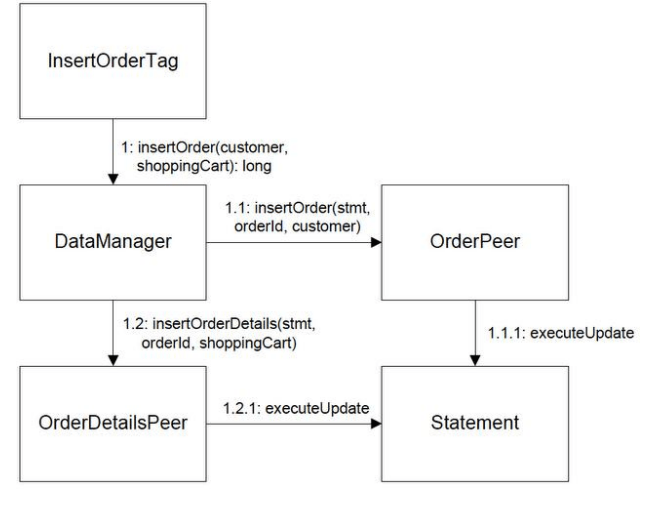
1. UML Communication/ Collaboration in Software Engineering:
Shows the relation between the object or parts in terms of sequence messages. They represent a combination of information taken from class; sequence and Use Case Diagrams define a system’s static structure and dynamics behavior.
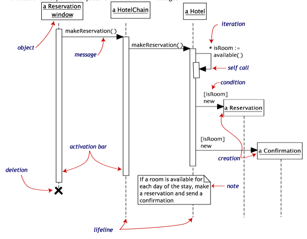
2. UML Sequence Diagram in Software Engineering:
Show objects communication with each other in terms of a sequence of messages. Also, it shows the lifespans of objects relative to those messages.